Monitoring, Simulation, and Operation: The Three EMS Run Modes
An EMS run mode is the state the control system is started in, and it decides whether commands reach real equipment. Monitoring polls every device and records data but issues nothing; simulation runs every task and algorithm against simulated device behavior and writes nothing to real hardware; operation runs the same stack against the real plant, and it is the only mode that moves power.
In brief
- Commission in monitoring, prove the configuration in simulation, and move to operation only when the equipment, the protection scheme, and the people on site are ready.
- The run state is shown in the header of every screen, with a live count of running tasks and task errors, so the state of the plant is always one glance away.
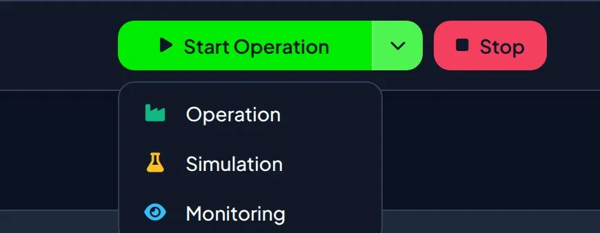
- Starting is a split button: the left half starts the selected mode and the chevron chooses it. On an idle system it defaults to operation, so read the label before pressing.
- Stopping runs the site’s shutdown task, which at the demonstration site ramps the PCS down before the safe state is applied. The EMS is not stopped until the header reads Idle.
- Control safety sits beneath every mode: interlocks block all dispatch including operator overrides, ramp limits bound how fast a command may move, and a device heartbeat lets equipment revert if the EMS goes silent.
What does each run mode actually do?
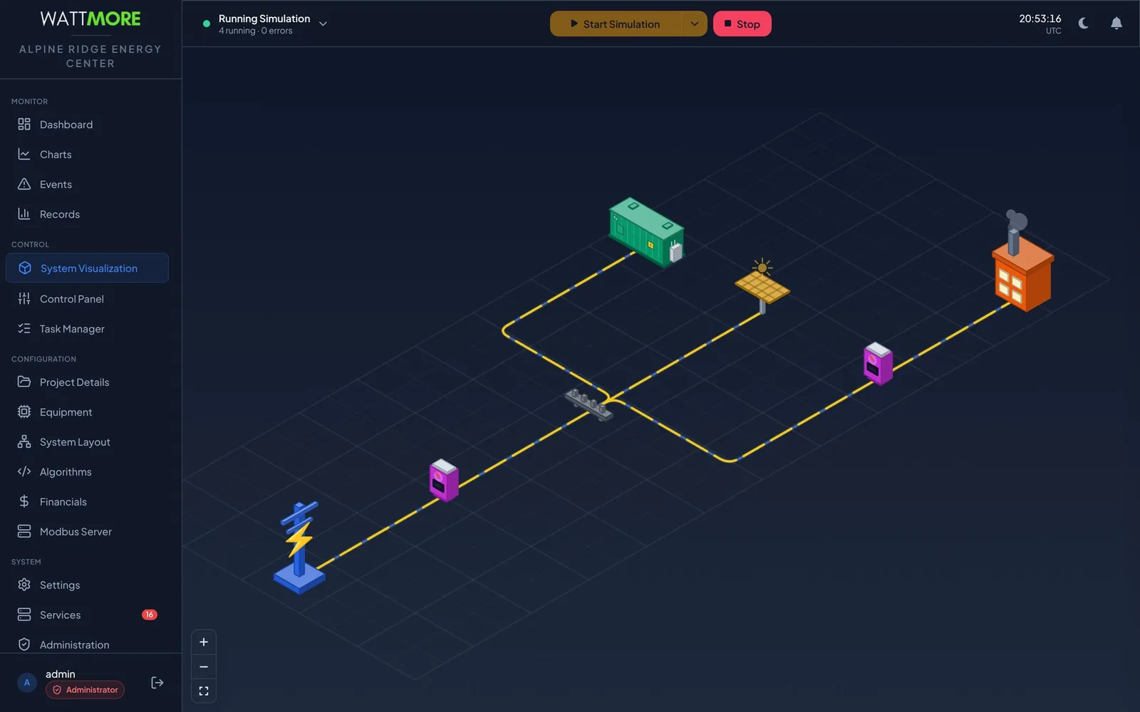
Every screen in the EMS shares a header that carries the run state control: a status button on the left, the start and stop buttons in the center, and the site clock on the right. The status button shows the state in words, Idle, Running Simulation, Running Operation, Running Monitoring, Starting, or Stopping, with a colored dot for the dashboard’s connection to the control system and a second line that counts running tasks and errors.
The three modes differ only in where commands go. Simulation runs the full control stack, every task and every algorithm, against a simulated plant. Sites use it to rehearse a dispatch strategy, to check that a newly activated algorithm behaves, and for operator training. Operation is live control: the same tasks and algorithms, with their commands reaching the plant. Monitoring reads and records without dispatching, which suits a plant being maintained by others, a control strategy under revision, or a site that only wants data logging.
| Mode | What it does | When a site uses it |
|---|---|---|
| Monitoring | Polls every device and records data. Issues no commands. | Commissioning, and any period when you want visibility without control. |
| Simulation | Runs the full control stack against simulated device behavior. Nothing is written to real equipment. | Proving a configuration, testing an algorithm change, training. |
| Operation | Runs the full control stack against the real plant. Commands reach the equipment. | Normal revenue operation. |
What are the run states between idle and running?
A start command is not instantaneous. The EMS moves through Starting, during which the site’s startup task runs, before it settles on a running mode. At the demonstration site the startup task verifies device communications and sets the PCS to standby. A stop moves through Stopping while the shutdown task runs and the recurring tasks are wound down. Two further states matter: Booting, while the control application comes up after an appliance restart and refuses commands, and EMS Disconnected, when the dashboard cannot reach the control system and displayed values are not live.
The status button expands into a lifecycle timeline that shows the whole run cycle as a pipeline, start, starting, started, running, stop, stopping, stopped, with the task boxes under each stage and a live badge on each. When the EMS is idle every task shows READY and the footer reads idle with no uptime, which is the quick way to confirm a site is genuinely stopped rather than transitioning.
| State | What the plant is doing |
|---|---|
| Idle | Nothing is dispatched. Devices are left as the shutdown routine set them. |
| Booting | Nothing yet. Start and stop commands are refused until this clears. |
| Starting | The startup task is preparing the site. |
| Running Simulation | No commands reach real hardware. |
| Running Operation | Live dispatch. Algorithms are commanding real power. |
| Running Monitoring | Devices are read and logged; nothing is dispatched. |
| Stopping | The shutdown task is bringing the site to its safe state. |
| EMS Disconnected | Unknown. Displayed values are not live; investigate before acting. |
How do you start and stop safely?
The start control is a split button. Its left half starts the selected mode and the chevron on the right chooses which mode that is. Choosing relabels and recolors the button, green for operation, amber for simulation, blue for monitoring, and starts nothing. Both halves are unavailable while a mode is already running or while the EMS is starting or stopping, and starting one mode while another runs is refused. On an idle system the default is operation, the mode that commands live hardware, so the label deserves a read before every press.
Stop always acts on whichever mode is running, and it is not a display action. The EMS runs the site’s shutdown task, then stops the recurring tasks. On a live site that ends revenue operation and hands the plant back to its local protection and controls. Coordinate with site staff before stopping, and wait for the header to read Idle rather than walking away during Stopping. If a message reports that the command could not be sent and the plant has not been commanded, nothing reached the plant; it is running exactly as it was.
- To confirm a start completed: the status button shows a settled state, the lifecycle timeline shows the startup task as DONE and the recurring tasks as RUNNING, the error count reads zero, and the events logged around the transition are clean.
- To confirm a stop completed: the status button reads Idle and every task in the lifecycle timeline shows READY.
- Auto start lets the EMS resume by itself after the appliance restarts, in the mode it was in when the appliance stopped. On a site whose last state was operation, that means live dispatch resumes without an operator present, so confirm it is what the site wants.
What sits beneath every mode?
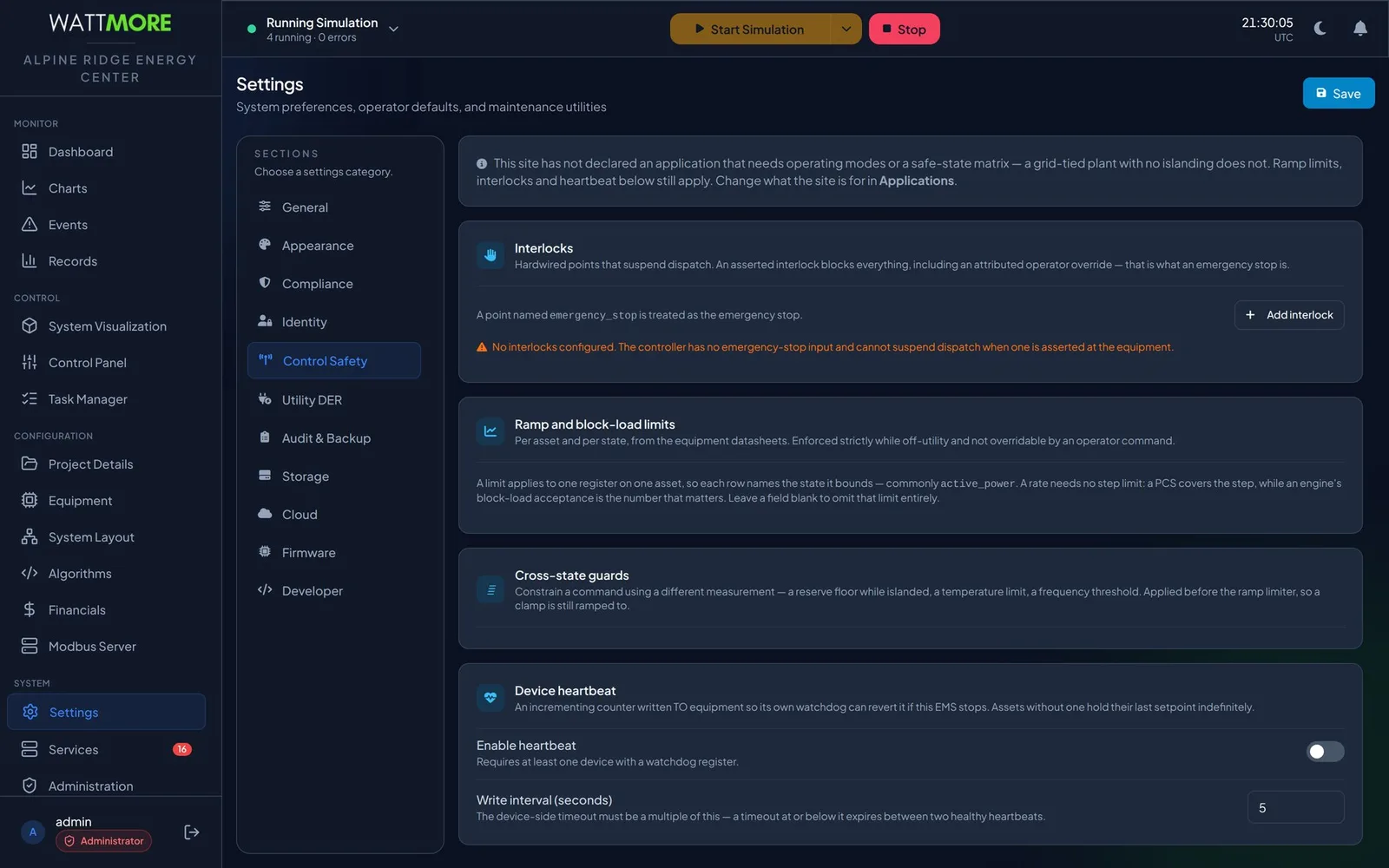
Control safety defines the limits inside which the controller may command the plant, regardless of what an algorithm or an operator asks for. An interlock is a hardwired point that suspends dispatch. When asserted it blocks everything, including an attributed operator override, which is what makes it an emergency stop rather than a request. A point named emergency_stop is treated as the site emergency stop, and a site with no interlock configured has no emergency stop input the controller can honor.
Ramp and block load limits come from equipment datasheets and bound how fast a command may move. They are enforced strictly while off utility and cannot be overridden by an operator command. Cross state guards constrain a command using a different measurement, a reserve floor while islanded, a temperature limit, a frequency threshold, and are applied before the ramp limiter so a clamped value is still ramped to rather than stepped to. The device heartbeat is an incrementing counter written to equipment so that the equipment’s own watchdog can revert if the EMS stops; assets without one hold their last setpoint indefinitely.
What does an operator watch while it runs?
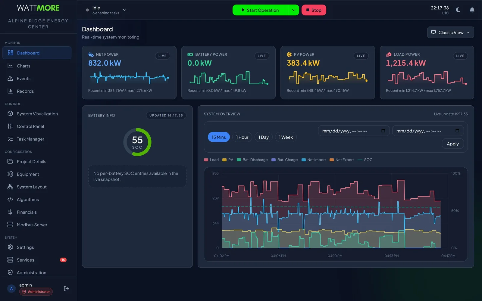
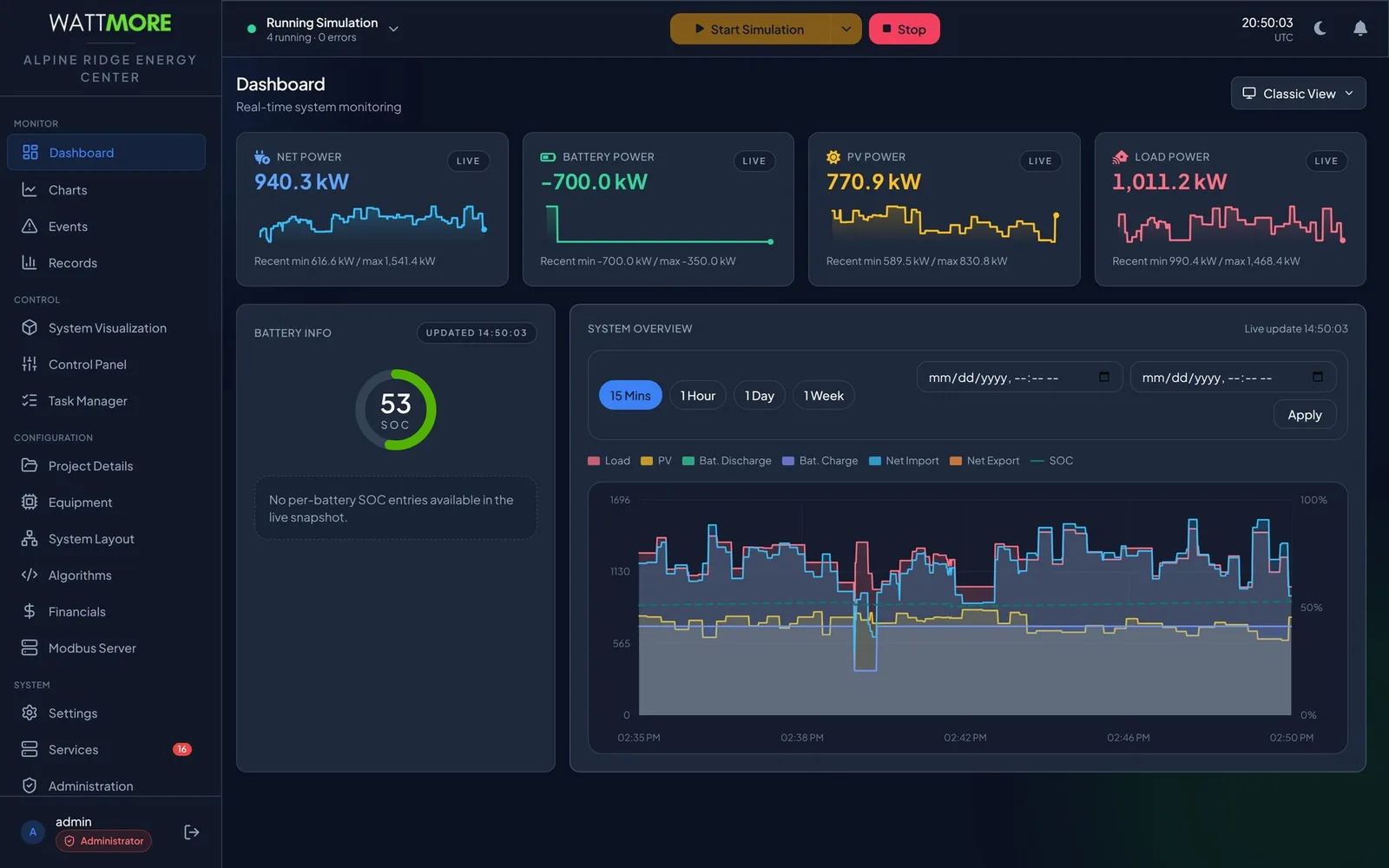
The Dashboard is the screen an operator leaves open all day. Four tiles across the top give instantaneous net power, battery power, PV power, and load power in kilowatts, each with a live badge, a ten minute sparkline, and the recent minimum and maximum. Two of the four are signed, and reading them the wrong way round is the most common misreading of the screen. Net power is positive when the site imports and negative when it exports. Battery power is positive when the battery discharges into the site and negative when it charges; a reading of minus 700 kW is a battery absorbing 700 kW.
A battery panel shows fleet state of charge as a ring, green above 30 percent, amber between 20 and 30, red below 20. The System Overview chart plots the whole plant on one pair of axes over fifteen minutes, an hour, a day, or a week, drawing each signed quantity as two positive bands so direction is read from which band is filled. Nothing on the Dashboard changes the plant; every control selects what you look at.
A five minute walk around a running site
If the system in front of you is already commissioned and running, this sequence tells you the state of the site.
- Read the header. Is the plant idle or running, in which mode, and are there task errors?
- Open Dashboard. Are the four power tiles live, and does the state of charge look plausible for the time of day?
- Open Events and filter to warnings and errors. Is anything active?
- Open Task Manager. Is every enabled task running, and is the error count zero?
- Open Services. Is every service healthy?
- Open Records and look at the last week. Is every day accounted for?
Intellect Operate
Intellect Operate is the WATTMORE energy management system shown in these screenshots. It runs monitoring, simulation, and operation from one header control, and enforces interlocks, ramp limits, and a device heartbeat beneath every algorithm.
Frequently asked questions
- Can an EMS be tested without risking the plant?
- Yes. Simulation runs every task and every algorithm against simulated device behavior and writes nothing to real equipment. Load and PV profiles and a fluctuation rate are configured per device, so a well configured simulation is a rehearsal of the real site rather than an abstract test. A site should run a full daily cycle in simulation without errors before it is allowed to dispatch.
- What happens to the battery when the EMS is stopped?
- Stop runs the site’s shutdown task first. At the demonstration site that task performs an orderly ramp down of the PCS before the platform’s safe state is applied. The converters are then left where the shutdown routine put them, and nothing further is commanded until the EMS is started again. On a live site this ends revenue operation, so it is coordinated with site staff.
- What is the difference between an interlock and pausing a task?
- Pausing a dispatch task is an operator action that leaves the plant at its last commanded setpoint with nothing updating it, and it stays paused until someone resumes it. An interlock is a hardwired point that suspends all dispatch when asserted, including operator overrides, and is honored regardless of what any algorithm or operator asks for. The interlock is the emergency stop; the pause is a maintenance convenience.
- Why does the start button default to operation?
- On an idle system the split button defaults to the mode a commissioned site normally runs in. Because operation is the only mode that commands live hardware, the manual instructs operators to read the button label and select the intended mode before pressing, and the button recolors to match the mode so the choice is visible from across a control room.
- Does the EMS resume after a power cycle?
- Only if auto start is enabled in Settings. With it on, the EMS returns to the mode it was in when the appliance stopped: a site in operation comes back in operation, a site in simulation comes back in simulation, and an idle site stays idle. With it off, the EMS always comes up idle and waits for an operator.
Sources
- INTELLECT EMS 4.0 Operator and Administrator Manual, Chapter 12: Starting and Stopping the EMS, WATTMORE, Inc.
- Energy Storage Handbook, Chapter 15: Energy Storage Management Systems, Sandia National Laboratories for the U.S. Department of Energy
- IEC 62443, Industrial Communication Networks, Security for Industrial Automation and Control Systems, International Society of Automation