Intellect PPC
WATTMORE's Power Plant Controller for BESS
A turnkey power plant controller built and delivered by WATTMORE as an add-on to Intellect Operate. IEEE 2800 compliant, hardware-agnostic, and production-ready with validated PSCAD and PSS/E models included.
Intellect Power Plant Controller is WATTMORE's latest product in the Intellect Operate lineup.
Available as an add-on to Intellect Operate for any BESS project. Includes validated PSCAD models, commissioning support, and ongoing updates.
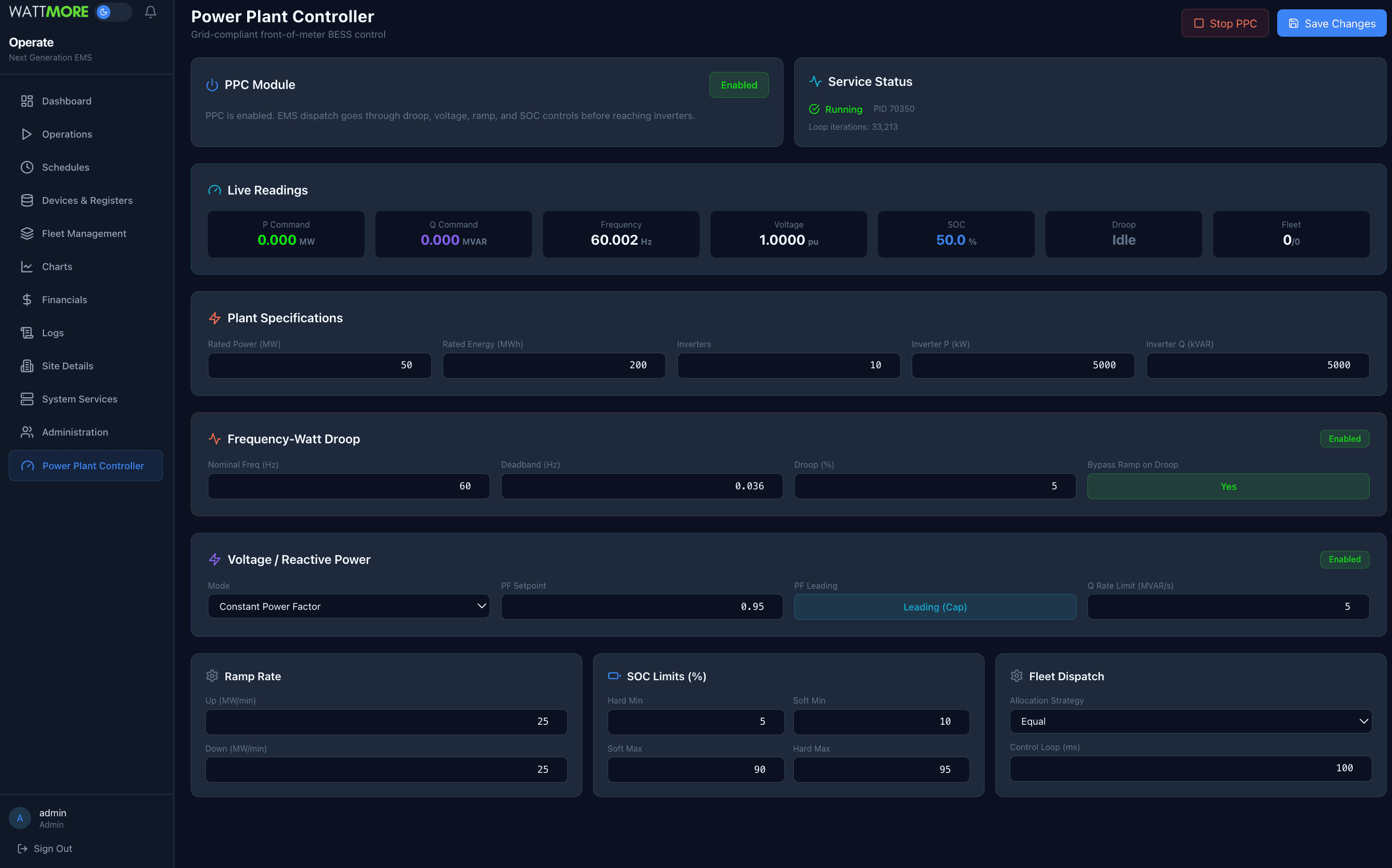
PPC Control Loop — Live Simulation
Watch how Intellect PPC processes grid signals in real time. Frequency deviations trigger droop response, voltage deviations trigger reactive power control, and every command is ramp-limited and SOC-protected before reaching the inverters.
Frequency Dip Event
Grid frequency drops below 59.97 Hz — watch the PPC respond with droop support
The grid is stable at 60.00 Hz. The EMS sends a 25 MW discharge command. The PPC passes it through with no modifications needed.
The PPC responds to frequency events within 100ms — faster than the EMS optimization cycle. Droop corrections bypass the normal ramp limiter so the battery can support the grid immediately.
What Is a Power Plant Controller?
A Power Plant Controller (PPC) is the real time supervisory control system that sits between the grid operator (or site level energy management system) and the individual power conversion equipment (inverters, converters). Every utility scale battery energy storage system (BESS) connected to the transmission or distribution grid requires a PPC to meet interconnection requirements defined by the grid operator, typically governed by IEEE 2800, NERC reliability standards, and the specific Interconnection Agreement (IA) for the site.
The PPC is responsible for ensuring the plant behaves as a single, predictable, grid compliant resource. It accepts high level dispatch commands (MW setpoint, voltage schedule, power factor target) and translates them into individual inverter level P and Q commands while enforcing grid code requirements: frequency response (droop), voltage regulation, ramp rate limits, and protection functions.
PPC Core Responsibilities
What Is an Energy Management System?
An Energy Management System (EMS) is the optimization layer that decides what the battery should do and when. It looks at electricity prices, demand charge schedules, solar forecasts, load patterns, and grid signals to determine the optimal dispatch strategy. The EMS operates on a longer time horizon (seconds to hours) and produces a power setpoint that represents the economically or operationally optimal action.
The EMS handles applications like peak demand shaving (reducing the facility's highest 15 minute power draw to lower demand charges), energy arbitrage (charging when electricity is cheap, discharging when expensive), solar self consumption, backup power management, and participation in wholesale energy markets.
EMS vs PPC: Division of Responsibility
- Determines optimal MW setpoint
- Reads electricity prices and tariffs
- Forecasts load and solar generation
- Manages schedules and time of use windows
- Calculates economic value of dispatch
- Operates on 1s to 15min timescales
- Enforces grid code on EMS setpoint
- Reads POI frequency and voltage
- Applies droop and voltage response
- Limits ramp rates to IA requirements
- Protects battery SOC boundaries
- Operates on 10ms to 100ms timescales
How the EMS and PPC Work Together
The EMS and PPC run as independent processes connected through Redis. The EMS writes a power setpoint. The PPC reads it, applies all grid compliance transformations, and dispatches the result to inverters. This separation ensures the PPC can always enforce safety and grid code requirements regardless of what the EMS requests. If the grid needs emergency frequency support, the PPC overrides the EMS setpoint immediately without waiting for the optimization layer.
System Architecture
PPC Internal Signal Chain
Each control loop iteration, the PPC reads inputs from Redis, processes the setpoint through a fixed sequence of control stages, and writes per inverter commands back to Redis. The stages execute in order. Each one transforms the power command before passing it to the next. This cascade architecture ensures grid code compliance is applied deterministically regardless of the upstream dispatch source.
PPC Control Pipeline (per loop iteration)
Frequency Watt Droop Response
Droop control is the primary frequency response mechanism required by virtually all grid codes for utility scale storage. When grid frequency deviates from nominal (60 Hz in North America, 50 Hz elsewhere), the battery injects or absorbs power proportionally to the deviation. This is a fast, autonomous response that does not wait for dispatch commands. It activates within the PPC control loop cycle time (100 ms default).
The droop percentage defines the sensitivity. A 5% droop on a 50 MW plant means the plant delivers full rated power when frequency drops by 5% of nominal (3 Hz on a 60 Hz system). A smaller droop percentage means more aggressive response. The deadband prevents the system from chasing normal frequency noise. The IEEE 2800 default deadband is ±36 mHz.
Droop Calculation
Droop Characteristic Curve
Inside the deadband the plant does not respond to frequency deviations (normal grid noise). Outside the deadband, response is linear with slope Kdroop.
Droop Configuration Parameters
droop_percentDroop slope as a percentage of rated power per nominal frequency. 5% is standard for BESS. Lower values give more aggressive response.
deadband_hzFrequency deviation threshold before response activates. IEEE 2800 default is 0.036 Hz (36 mHz). Prevents response to normal grid frequency noise.
max_response_mwOptional cap on droop output. If unset, defaults to plant rated power. Useful for limiting frequency response to a contracted capacity.
bypass_ramp_limiterWhen true, droop response bypasses the ramp rate limiter for fastest possible frequency support. Most grid codes require this.
Voltage and Reactive Power Control
Reactive power (Q, measured in MVAR) controls voltage at the point of interconnection. Unlike active power which transfers real energy, reactive power manages the electromagnetic field relationships in AC systems. Grid operators require BESS plants to support POI voltage through one of three modes, selectable based on the interconnection agreement.
Mode 1: Constant Power Factor
Q follows P to maintain a fixed power factor. Leading (capacitive) Q injects reactive power. Lagging (inductive) absorbs it.
Mode 2: Voltage Regulation (PI)
A PI controller adjusts Q to hold POI voltage at a setpoint (typically 1.0 pu). A deadband prevents hunting around the target.
Mode 3: Volt VAR Curve
A piecewise linear Q(V) characteristic curve. Four voltage breakpoints define the shape. Q is positive (inject) at low voltage, zero in the deadband, negative (absorb) at high voltage.
Q Rate Limiting
All three voltage modes share a common output rate limiter. The Q command is slew rate limited to prevent sudden reactive power swings that could cause POI voltage transients. Default limit is 5 MVAR/s, configurable per interconnection agreement. The rate limiter applies after mode calculation but before the command is written to inverters.
Ramp Rate Limiting
Interconnection agreements specify maximum rates of change for active power, typically in MW/min. This prevents the BESS from causing sudden power swings on the grid that could affect power quality for other connected customers. Separate up and down rates can be configured since some grid codes have asymmetric requirements (e.g., faster ramp down for safety, slower ramp up to prevent voltage sags).
Ramp Limiter Algorithm
When droop response is active and bypass_ramp_limiter is enabled, the ramp limiter is bypassed entirely so the plant can deliver full speed frequency support. This is standard practice. Grid frequency events require sub second response, and the interconnection ramp limit is intended for economic dispatch changes, not emergency grid support.
State of Charge Protection
The SOC limiter protects the battery from over discharge and over charge by smoothly derating power commands as SOC approaches the configured boundaries. This uses a soft/hard limit system. Between the soft and hard limit, available power ramps linearly from 100% to 0%. This prevents sudden power cutoffs that would violate ramp rate requirements and provides a smooth degradation curve.
SOC Limit Regions
Derating Formulas
Fleet Dispatch and Inverter Allocation
After the PPC computes the final plant level P and Q commands, the fleet allocator distributes these across all online inverters. Faulted inverters are excluded from allocation, and their commands are set to zero. Three allocation strategies are available.
Equal Distribution
Divides plant command equally among all online inverters, clamped to each inverter's rating. Simplest strategy. Works well when all inverters are identical.
Proportional Distribution
Allocates proportionally to each inverter's rated capacity. Useful for mixed fleets with different inverter sizes.
Priority Distribution
Fills inverters sequentially to capacity before moving to the next. Minimizes active inverters. Useful for maintenance windows or efficiency optimization.
Redis Data Flow and Key Map
The PPC reads all inputs from Redis (published by the DAQ service) and writes all outputs to Redis (consumed by the PCS actuator and monitoring). It never connects directly to any hardware device. This architecture means the PPC can be stopped, started, or restarted without affecting data acquisition or device communication.
Redis Keys Used by PPC
| Key | Direction | Description |
|---|---|---|
| {poi_meter}:latest | Read | POI frequency, voltage, power (from DAQ) |
| {bms}:latest | Read | Battery SOC, voltage, temperature (from DAQ) |
| controller:power_setpoint | Read | EMS active power setpoint in watts |
| ppc:p_setpoint_w | Read | PPC specific setpoint override (optional) |
| ppc:curtailment_mw | Read | Grid operator curtailment ceiling |
| ppc:p_cmd_w | Write | Plant level active power command |
| ppc:q_cmd_var | Write | Plant level reactive power command |
| ppc:inverter:{id} | Write | Per inverter P/Q commands (fleet dispatch) |
| ppc:status | Write | Service status, live readings, loop count |
Glossary of Terms
Power Plant Controller. The real time supervisory controller for the entire BESS plant.
Energy Management System. Optimization layer that determines what the battery should do.
Point of Interconnection. The electrical boundary where the plant connects to the grid.
Battery Energy Storage System. The complete storage plant including batteries, inverters, and controls.
Power Conversion System. The inverter/converter that converts DC battery power to AC grid power.
Battery Management System. Monitors cell voltages, temperatures, and SOC. Enforces battery safety limits.
State of Charge. Battery energy level as a percentage (0% = empty, 100% = full).
Megawatt. Unit of active (real) power. 1 MW = 1,000 kW.
Mega Volt Ampere Reactive. Unit of reactive power, which controls voltage.
Per unit. Normalized value where 1.0 = nominal. Used for voltage (1.0 pu = rated voltage).
Proportional frequency response characteristic. Slope defines MW response per Hz deviation.
Frequency range around nominal where no droop response occurs (filters grid noise).
Power Factor. Ratio of real power to apparent power. PF = P / sqrt(P² + Q²). Range 0 to 1.
Automatic Generation Control. Grid operator signal that dynamically adjusts plant output for area frequency regulation.
Interconnection Agreement. Contract between plant owner and utility defining technical requirements.
Standard for interconnection of inverter based resources. Defines frequency/voltage response requirements.
Power Systems Computer Aided Design. Industry standard electromagnetic transient (EMT) simulation software by Manitoba Hydro International. Used for microsecond level inverter and Power Plant Controller dynamics validation.
Power System Simulator for Engineering. Siemens transmission planning software for power flow, transient stability, and contingency analysis. Required by all major ISOs for interconnection studies.
Electromagnetic Transient. High fidelity time domain simulation capturing fast switching and control dynamics at microsecond resolution. PSCAD is the standard EMT tool.
User Defined Model. Custom coded dynamic model in PSS/E that replicates specific Power Plant Controller control behavior beyond what generic library models can represent.
WATTMORE Has Validated PSCAD and PSS/E Models
Utilities and ISOs require validated simulation models before any storage project connects to the grid. These studies run on two industry standard platforms: PSCAD for electromagnetic transient (EMT) analysis and PSS/E for power flow and transient stability. WATTMORE has invested in building validated models of Intellect PPC in both platforms. Most EMS and Power Plant Controller providers have not.
PSCAD, developed by Manitoba Hydro International, simulates inverter dynamics and Power Plant Controller control behavior at microsecond resolution. WATTMORE's PSCAD model is an exact replica of Intellect PPC - same inputs, same outputs, same control logic. PSS/E, developed by Siemens, models system wide power flow and electromechanical stability. WATTMORE provides both generic library and User Defined Models for PSS/E interconnection studies.
PSCAD Model
Electromagnetic transient simulation at microsecond resolution. Validates fault ride through, droop response, voltage control dynamics, and sub synchronous interactions.
PSS/E Model
Power flow and transient stability simulation for system wide interconnection studies. Validates steady state behavior, contingency response, and voltage stability.
Building these models requires significant investment in industry standard simulation software, advanced power systems engineering expertise, and months of development and validation work. WATTMORE has made this investment because interconnection compliance is not optional - it is the difference between a project that connects to the grid and one that sits in the queue. When you choose Intellect PPC, your interconnection study package arrives complete.
Power Plant Controller FAQ
What is a power plant controller?
A power plant controller (PPC) is a real-time control system that sits between the grid operator and the inverters at a power plant. The power plant controller receives dispatch commands from the utility or ISO and translates them into setpoints for each inverter while enforcing grid compliance requirements like frequency droop, voltage regulation, and ramp rate limits. Every utility-scale battery storage and solar project needs a power plant controller to meet interconnection requirements and IEEE 2800 standards.
What is a storage power plant controller?
A storage power plant controller is a power plant controller specifically designed for battery energy storage systems (BESS). Unlike solar-only controllers, a storage power plant controller must manage bidirectional power flow (charge and discharge), state of charge protection, and complex dispatch optimization. WATTMORE's Intellect PPC is a storage power plant controller that handles droop response, voltage control, ramp limiting, SOC protection, and fleet dispatch for battery storage projects of any size.
What is the difference between a power plant controller and an energy management system?
A power plant controller (PPC) and an energy management system (EMS) serve different roles in the control hierarchy. The energy management system is the optimization layer—it decides when to charge, discharge, or participate in grid services to maximize revenue. The power plant controller is the compliance layer—it enforces grid requirements like frequency droop, voltage regulation, and ramp rate limits on every command before it reaches the inverters. WATTMORE integrates both the PPC and EMS into a single platform called Intellect Operate, eliminating the integration risk of using separate vendors.
Do I need a power plant controller for my BESS project?
Yes. Every utility-scale battery energy storage system requires a power plant controller for interconnection. Utilities and ISOs require the PPC to enforce grid compliance including frequency-watt droop response, voltage and reactive power control, ramp rate limiting, and curtailment. Without a power plant controller, your project cannot pass interconnection studies or operate on the grid. FERC Order 2023 and IEEE 2800 have made PPC requirements more stringent than ever.
What is IEEE 2800 and how does it relate to power plant controllers?
IEEE 2800 is the standard for interconnection and interoperability of inverter-based resources (IBR) with the power grid. It defines the performance requirements that every power plant controller must meet, including frequency ride-through, voltage ride-through, active power-frequency response (droop), reactive power-voltage response, and ramp rate control. WATTMORE's Intellect PPC is designed to be fully IEEE 2800 compliant, with validated PSCAD and PSS/E models that prove compliance to utilities and ISOs.
What is frequency droop response in a power plant controller?
Frequency droop response is a core function of any power plant controller. When grid frequency deviates from the nominal 60 Hz, the PPC automatically adjusts active power output to help stabilize the grid. For example, if frequency drops below the deadband (typically 59.97 Hz), the PPC commands batteries to discharge additional power proportional to the frequency deviation. The droop gain (typically 3-5%) determines how aggressively the PPC responds. This happens in real-time without waiting for dispatch commands from the grid operator.
Can a power plant controller manage multiple inverters and batteries?
Yes. A power plant controller must distribute dispatch commands across all inverters at a site, which is called fleet dispatch. WATTMORE's Intellect PPC supports three allocation strategies: equal distribution (same setpoint to all inverters), proportional distribution (based on each unit's capacity and SOC), and priority-based allocation (dispatching specific units first based on SOH or operational priority). This ensures optimal utilization across the entire fleet.
What PSCAD and PSS/E models does WATTMORE provide for the power plant controller?
WATTMORE provides validated PSCAD (electromagnetic transient) and PSS/E (power flow and transient stability) simulation models of Intellect PPC. These models are required by every major ISO and utility—including CAISO, ERCOT, MISO, PJM, SPP, and ISO-NE—for interconnection studies. Having pre-validated power plant controller models eliminates months of delay and significant cost from your interconnection timeline. WATTMORE's models cover droop response, voltage control, ramp limiting, and fault ride-through behavior.
Why should the power plant controller and EMS come from the same vendor?
When the power plant controller and energy management system come from different vendors, every dispatch command must cross a vendor boundary—introducing latency, finger-pointing during failures, and complex integration testing. WATTMORE integrates the PPC and EMS into a single platform (Intellect Operate) so the optimization layer and compliance layer share the same data bus, the same control loop, and the same support team. This eliminates integration risk and ensures the EMS never sends a command the PPC cannot safely execute.
How does a power plant controller handle ramp rate limiting?
Ramp rate limiting is a grid requirement that prevents battery storage systems from changing power output too quickly, which can destabilize the grid. The power plant controller enforces separate ramp rates for increasing power (ramp-up) and decreasing power (ramp-down), measured in MW per minute or percentage of rated capacity per minute. WATTMORE's Intellect PPC applies asymmetric ramp rate limits with a droop bypass—meaning during a frequency event, the PPC can respond faster than the normal ramp limit allows, as required by IEEE 2800.
How much does a power plant controller cost?
The cost of a power plant controller depends on project size, compliance requirements, and whether the PPC is standalone or integrated into an energy management system. Standalone power plant controllers from third-party vendors typically add significant cost plus ongoing integration and maintenance expenses. WATTMORE's approach bundles the power plant controller directly into Intellect Operate, so there is no separate PPC hardware or licensing cost—the power plant controller is included as part of the EMS platform, reducing total project cost and eliminating vendor integration risk.
What is the difference between a power plant controller and SCADA?
SCADA (Supervisory Control and Data Acquisition) is a monitoring and data collection system that provides visibility into plant operations. A power plant controller is an active real-time control system that enforces grid compliance on every dispatch command. SCADA tells you what is happening at the plant. The power plant controller decides what the plant is allowed to do based on grid requirements. WATTMORE's Intellect Operate includes both SCADA and power plant controller functionality in a single integrated platform.
Who needs a power plant controller?
Any project connecting an inverter-based resource to the grid needs a power plant controller. This includes utility-scale battery storage (BESS), solar farms, hybrid solar-plus-storage projects, and wind farms. ISOs and utilities including CAISO, ERCOT, MISO, PJM, SPP, and ISO-NE all require power plant controller functionality for interconnection approval. Even smaller commercial and industrial storage projects increasingly need power plant controller capabilities as utilities tighten interconnection requirements under IEEE 2800 and FERC Order 2023.
What is a BESS power plant controller?
A BESS power plant controller is a power plant controller built specifically for battery energy storage systems. It handles the unique challenges of bidirectional power flow, state of charge management, and coordination between the energy management system and the grid. A BESS power plant controller must manage charging and discharging while simultaneously enforcing frequency droop, voltage regulation, and ramp rate compliance. WATTMORE's Intellect PPC is a BESS power plant controller with full IEEE 2800 compliance and validated PSCAD and PSS/E models.
Can a power plant controller work with any inverter brand?
A well-designed power plant controller should be hardware-agnostic and work with any inverter manufacturer. WATTMORE's Intellect PPC communicates with inverters via industry-standard Modbus TCP/IP protocol with flexible register mapping, supporting all major inverter brands including Dynapower, SMA, EPC Power, Sungrow, Power Electronics, and others. This vendor-agnostic approach means you are never locked into a single inverter manufacturer.
Ready to Deploy Intellect PPC?
Intellect Operate integrates EMS, SCADA, and Power Plant Controller in a single platform. One deployment, one interface, one support team. Validated PSCAD and PSS/E models included.